 dB & DEGREES obtains the “Young Innovative Company” (JEI) status
 dB & DEGREES announces the success of its capital increase of 80,000 euros
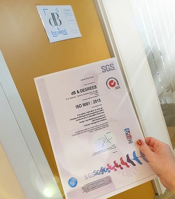 dB & DEGREES obtains ISO 9001: 2015 certification
 dB & DEGREES is now at Bordeaux
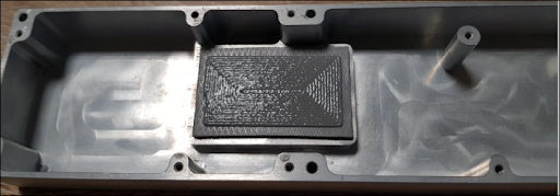 How to solve the problems of mechanical buckling of an electronic board
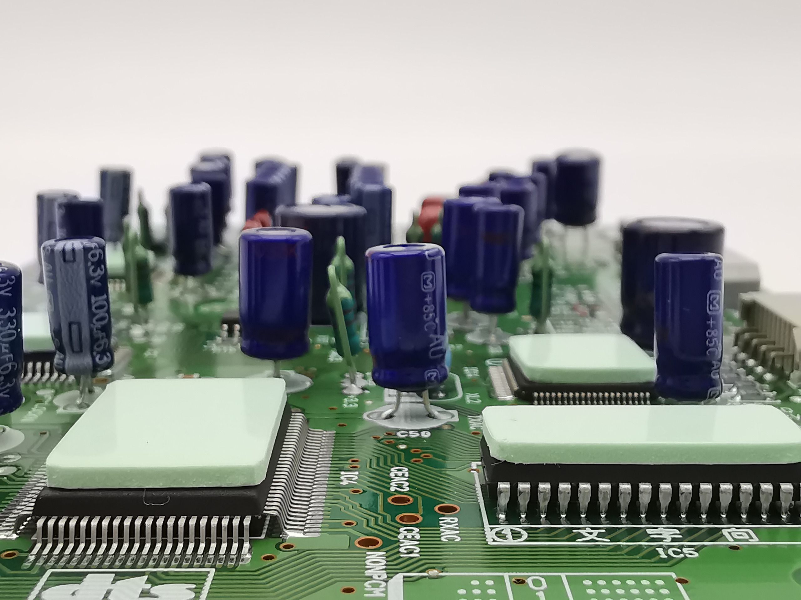 TIM (thermal interface material): are the thermal characteristics reliable?
 Find an effective solution to corrosion issues
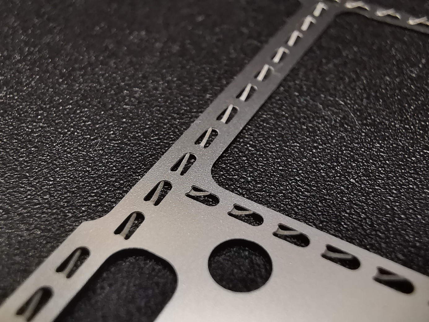
Posted on January 28, 2020
To limit the interference in susceptibility and emission towards electronic components of a printed circuit / PCB, the electromagnetic shielding of the PCB requires a specific cover that is assembled on the circuit and generally provided with several cavities. These cavities individually faradize the different parts of the circuit and the overall PCB towards the outside.
But the junction between this multi-cavity cover and the PCB board is never perfect ( tightening / mechanical tolerances), while it is an essential element to ensure an effective shielding = this interface must not present any slots likely to pass unwanted signals.
A customer in the telecoms market recently asked us to carry out the electromagnetic shielding on an aluminum casting.
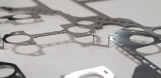
Use-case of a metal gasket
The usual contact solutions (screw tightening, re-machining of contact surfaces, etc.) had been explored by this client but were not possible due to their cost and the mechanical space constraints:
- Securing the two elements via a large number of screws reduces the space available in the equipment, increases the weight of the assembly, and increases its assembly cost
- Machining is an expensive process and may prove to be insufficient for satisfactory jointing
- Molding-rectification is also an expensive process and may also prove to be insufficient
The client then planned to involve us on his aluminum casting to deposit an electrically conductive gasket FIP (FORM IN PLACE).
Under an NDA (Non disclosure Agreement), he entrusted us with his mechanical 3D drawings and his PCB layout drawings. We found that in this project (K-band application), the required mechanical tolerances were a real technical challenge that a traditional FIP gasket could not guarantee in the serial manufacturing phase. Since there was no fluid tightness constraint (IP), we therefore recommended an alternative to the FIP gasket: the metal gasket.
Our client was convinced of the many advantages (technical and economic) and the maturity of the process: he had already experimented with this metal gasket technology in previous projects on behalf of another company. Integrating it into this new, very innovative and technically demanding project, turned out to be the right choice.
The walls of the cavities could be refined and the number of screws could be reduced. These technical advantages have left even more room for the PCB.
Our added values on this project:
- Advice on the choice of the most relevant technologies to respond to their problems
- Design of the architecture of the gasket to integrate between the mechanics and the PCB (bridges, clamps, holes….)
- Study of the location and shape of the springs according to the shields expected in each of the different cavities
- Fast 3D modeling of the metal gasket for verification by the customer of the gasket integration in his assembly
The metal gasket in few words
For this type of problem, a metal gasket can be a very good solution. The advantages of the metal gasket are numerous :
- A small footprint in the thickness, in the range of 0.15 mm
- A height compensation capacity of 0.3mm to 1.6mm (if the springs are bent in both directions)
- On a same gasket, it is possible to adapt different shielding attenuation levels by locally modifying the spacing of the springs (pitch), and / or by making a double row of springs.
- The thicknesses of the springs can be locally reduced to minimize the compression forces
- It is a part which is used as much on multi-cavity shielding covers made of metallized plastic as on metal covers
Epilogue
Our client is currently in series production with our metal gaskets.
Our team collaboration is going so well that his colleagues are already asking us for a brand new telecom project (in Q band) which will certainly use this interfacing solution.
Note that if the appropriate solution had been an electrically conductive FIP gasket, we would as well have answered it. We will tell you more about that technology in a future article!